Injection moulding is one of the very trusted manufacturing processes for producing plastic parts, and the style of the tooling plays a crucial role in the quality, efficiency, and cost-effectiveness of the production. Injection moulding tooling design involves creating the moulds that shape molten plastic into finished components, ensuring accurate dimensions, smooth surface finishes, and minimal defects. A well-designed tool not merely reduces production problems such as for instance warping, sink marks, or flash but additionally maximizes the lifespan of the mould and minimizes maintenance costs. Understanding the principles and considerations of tooling design is essential for manufacturers, engineers, and product developers aiming to create high-quality parts consistently.
The building blocks of a fruitful mould design is based on understanding the material properties of the plastic used and the geometry of the part. Tooling designers must account fully for shrinkage, flow patterns, cooling rates, and ejection mechanisms to ensure the final part meets dimensional tolerances. Gate locations, runner systems, and venting are critical aspects that influence the filling of the mould and the caliber of the part. Additionally, proper attention must certanly be directed at draft angles, which allow easy ejection without damaging the component. By adhering to these principles, designers can prevent common defects such as short shots, sink marks, or warpage.
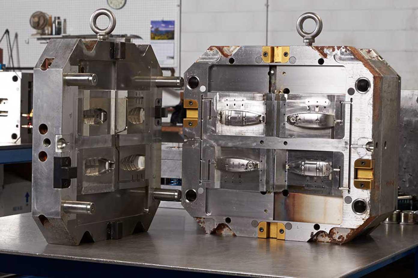
The decision of tooling materials is another important factor in injection moulding design. High-quality steels such as for example P20, H13, or stainless steel are commonly used for their durability, resistance to wear, and capability to withstand high pressures. Tooling designers also consider components like ejector pins, cooling channels, slides, and inserts to custom-made airline plastics optimize production efficiency. Cooling system design is especially important, as it directly affects cycle times and part quality. Properly designed cooling channels ensure uniform temperature distribution, reducing residual stresses and minimizing warping. By carefully selecting materials and components, tooling designers can extend mould life and improve overall production reliability.
Modern injection moulding tooling design relies heavily on computer-aided design (CAD) and simulation software. Tools like SolidWorks, AutoCAD, or Moldflow allow designers to visualize the mould, simulate plastic flow, identify potential defects, and optimize gate placement before actual manufacturing. Prototyping using 3D printing or soft tooling can further validate the style, assisting to catch issues early and reduce costly rework. Incorporating simulation and prototyping in the style process ensures faster development cycles, reduces production errors, and improves the entire quality of the ultimate product.
A well-optimized injection moulding tool enhances production efficiency by reducing cycle times, minimizing material waste, and simplifying maintenance. Designers often incorporate modular tooling components, multi-cavity designs, and advanced cooling techniques to improve output without compromising part quality. Regular maintenance schedules and careful monitoring of wear also ensure long-term performance of the mould. Ultimately, effective tooling design balances functionality, cost, and manufacturability, enabling companies to create high-quality plastic parts consistently and profitably. A proper method of injection moulding tooling design is therefore essential for manufacturers seeking competitive advantage in the plastic parts industry.